Greg
New Member

Posts: 8
|
Post by Greg on Jan 18, 2024 2:27:01 GMT
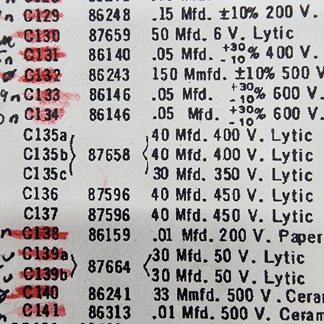
I am replacing the caps in the HFMA2 amplifier out of my Seeburg 201 and I noticed something odd with the multi-section electrolytic can capacitor. Here, you can see that the triangle post is the 30 MFD cap.  Underneath, you can clearly see the triangle noting the 30 MFD post (I confirmed the shapes on the other posts). The 2.7K resistor is wired between the two 40 MFD posts and the 39K resistor is wired between the 30 and 40 MFD posts.  But according to the schematic, the resistors should be wired the other way around, with the 2.7K resistor wired between the 30 and 40 MFD posts and the 39K between the 40 MFD posts.    So who do I trust? Did someone make an error during assembly or repair? Or is the schematic wrong? |
|
|
|
Post by jukeboxmarty on Jan 18, 2024 4:09:50 GMT
The amp is wired correctly. They just mixed up the symbols on the schematic. The 30 MFD goes to the 230 VDC circuit.
|
|
|
|
Post by jukenorman on Jan 18, 2024 10:00:22 GMT
While I agree with Marty that the 30uF would go to the 230VDC, I doubt that there would be any material difference if it was connected the other way round. The tolerance on these caps was large and these days when they are replaced, you have to make a best approximation from what is available to you.
Norman.
|
|
Greg
New Member

Posts: 8
|
Post by Greg on Jan 18, 2024 13:04:02 GMT
The amp is wired correctly. They just mixed up the symbols on the schematic. The 30 MFD goes to the 230 VDC circuit. Thank you! |
|
Greg
New Member

Posts: 8
|
Post by Greg on Jan 18, 2024 13:05:00 GMT
While I agree with Marty that the 30uF would go to the 230VDC, I doubt that there would be any material difference if it was connected the other way round. The tolerance on these caps was large and these days when they are replaced, you have to make a best approximation from what is available to you. Norman. I figured as much, just wanted to make sure I get it right since I'm going through all this trouble. |
|